Thermal Expansion of Stainless Pipe: Allowances for Long Runs
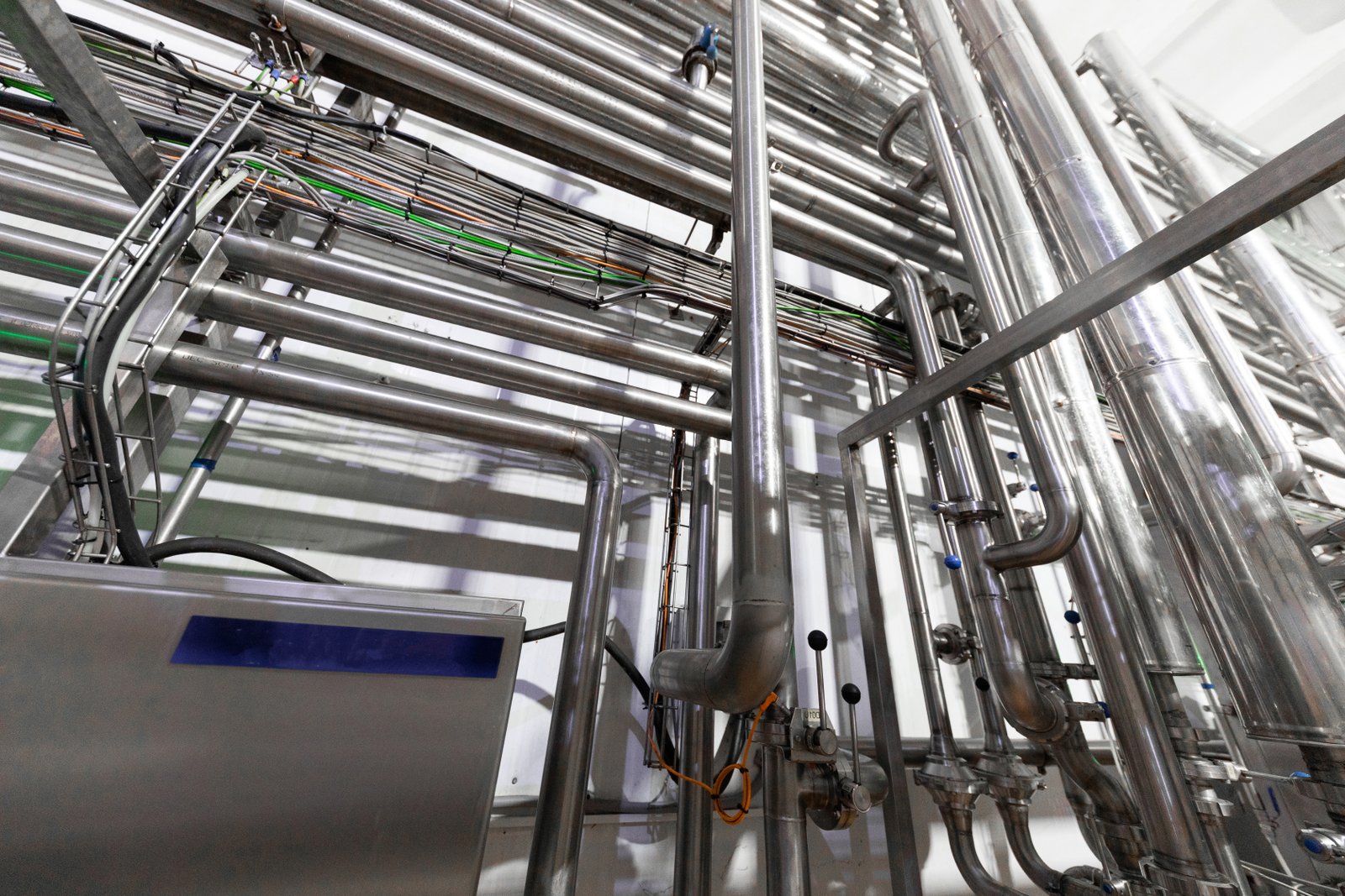
Are you designing a long-run piping system and worried about the hidden forces of nature? The immense stress from thermal expansion in трубы из нержавеющей стали1 can lead to buckling, leaks, and catastrophic failures, causing costly downtime. Understanding how to properly accommodate this movement is crucial.
Thermal expansion is the tendency of stainless steel pipes to change in length in response to temperature variations. Governed by the material's coefficient of thermal expansion, this predictable growth or shrinkage is a critical design factor, especially for long pipelines subjected to significant temperature changes.
This physical property might seem straightforward, but its implications for large-scale industrial and construction projects are profound. Ignoring it can transform a durable, corrosion-resistant material into a source of immense mechanical stress. In my work at MFY, I’ve seen how a lack of foresight in this area can lead to preventable and expensive problems for otherwise well-executed projects.
The challenge lies in the dual nature of stainless steel; we select it for its strength and resilience, yet its inherent physical properties, like a relatively high coefficient of thermal expansion compared to carbon steel, demand meticulous engineering. In industries from chemical processing to food and beverage, where temperature cycles are a daily operational reality, this isn't just a detail—it's central to system longevity and safety. Let's dive deeper into why this matters and how to manage it effectively.
What are the fundamental facts about thermal expansion in stainless steel pipes?
Are you concerned that a gap in your fundamental knowledge of thermal physics could compromise your piping project? Overlooking the basic principles of how stainless steel behaves with temperature changes can lead to design flaws that surface as costly, operational failures. Let's establish a clear and solid foundation.
Stainless steel pipes expand when heated and contract when cooled, a movement dictated by their coefficient of thermal expansion (CTE), overall length, and the temperature differential. Crucially, common austenitic grades like 304 and 316 expand approximately 50% more than carbon steel, a vital engineering consideration.
These scientific facts are not merely academic; they have direct, tangible consequences in the real world. I recall a project with a valued partner in Southeast Asia’s food processing industry. They were installing a new line for products that required frequent steam-in-place (SIP) cleaning, a process involving rapid temperature increases. The initial design, provided by a third party, had underestimated the thermal growth during these cycles. Within months of commissioning, they observed noticeable warping in several long pipe runs, putting stress on welded joints and threatening the sterile integrity of the system. This experience was a stark reminder that a successful project hinges on translating theoretical principles into practical application. Understanding these fundamentals is the first and most critical step in engineering a resilient piping system that can withstand the rigors of its operational life, avoiding the kind of costly retrofits this client had to undertake. It’s about building it right the first time.
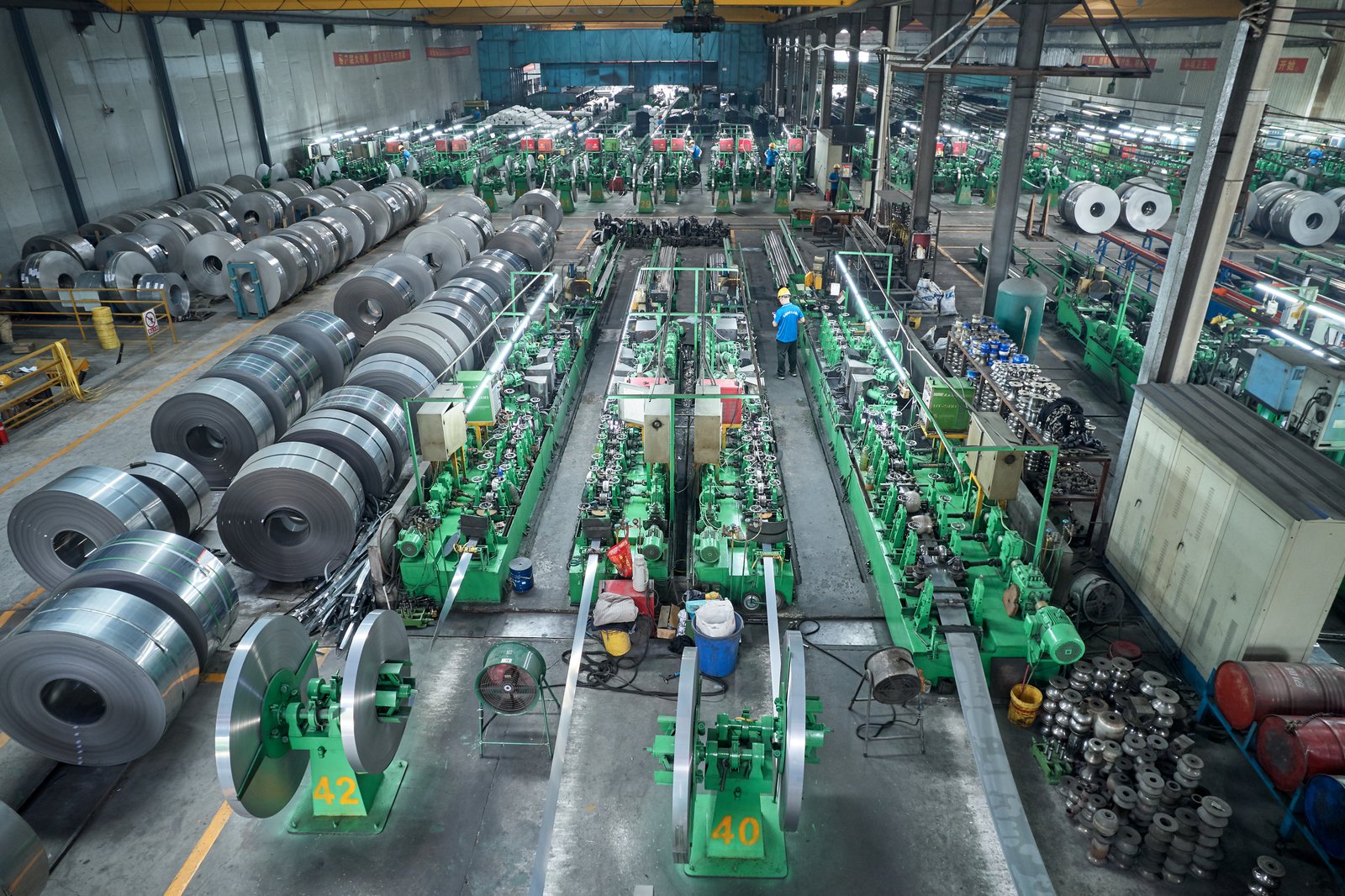
A comprehensive grasp of the fundamentals empowers engineers and project managers to make informed decisions that ensure long-term reliability. The science of thermal expansion is predictable, and by mastering its core components, we can design systems that work with physics, not against it. This involves looking closely at the material's intrinsic properties, the mathematics that govern its behavior, and the subtle factors that can influence outcomes in real-world applications.
The Coefficient of Thermal Expansion (CTE): A Closer Look
The coefficient of thermal expansion, often denoted by the Greek letter alpha ($\alpha$), is an intrinsic material property that quantifies how much a material expands per unit of length for each degree of temperature change. It’s a fundamental value that forms the basis of all thermal expansion calculations. For engineers, the CTE is not just a number in a textbook; it's a critical variable that directly impacts design choices, from material selection to the specification of support structures and flexibility solutions.
A crucial point of differentiation lies in the comparison between various piping materials. Austenitic stainless steels, such as the widely used grades 304 and 316, possess a CTE of approximately $16 \times 10^{-6}$ meters per meter per degree Celsius (m/m°C). In contrast, carbon steel, a common alternative, has a significantly lower CTE of around $12 \times 10^{-6}$ m/m°C. This 50% difference is not trivial; it means that for the same length and temperature change, a stainless steel pipe will grow half as much again as a carbon steel one, a fact that has profound implications for stress analysis and system design.
The chemical composition of the alloy is the primary determinant of its CTE. In stainless steels, the nickel content plays a particularly significant role. Higher nickel content, characteristic of the austenitic grades, generally leads to a higher CTE. This is why different families of stainless steel—austenitic, ferritic, duplex—exhibit different thermal behaviors. At MFY, we ensure our clients have precise material data sheets for the specific grades they purchase, because we understand that this level of detail is essential for accurate engineering and the prevention of future system failures.
Calculating Linear Expansion: The Core Formula
The actual change in a pipe's length ($\Delta L$) can be precisely calculated using a straightforward formula: $\Delta L = \alpha \times L_0 \times \Delta T$. In this equation, $\alpha$ represents the coefficient of thermal expansion, $L_0$ is the original length of the pipe run at the installation temperature, and $\Delta T$ is the change in temperature from the initial state to the final operating or shutdown state. This formula is the cornerstone of thermal design, transforming abstract material properties into a tangible, measurable length that the system must accommodate.
To illustrate, let's consider a practical example. Imagine a 100-meter run of Type 316 stainless steel pipe, installed at an ambient temperature of 20°C, which will operate at a fluid temperature of 100°C. The temperature change, $\Delta T$, is $80^\circ\text{C}$ ($100^\circ\text{C} - 20^\circ\text{C}$). Using the CTE for 316 SS (~$16.0 \times 10^{-6}$ m/m°C), the calculation is: $\Delta L = (16.0 \times 10^{-6}) \times 100 \text{ m} \times 80^\circ\text{C} = 0.128$ meters. This means the pipe will expand by 128 millimeters, or over 5 inches. This is a significant amount of movement that, if restrained, will generate immense force.
Accurately determining the $\Delta T$ is paramount. It’s not just about the maximum operating temperature. Engineers must consider the full range, from the lowest possible ambient temperature during shutdown (e.g., in a cold climate) to the highest temperature from either the process fluid or external sources like steam cleaning. A contractor we partnered with on a chemical plant project in India initially overlooked the low nighttime installation temperatures. Their initial calculations, based on average daytime temperatures, underestimated the total $\Delta T$, leading to a last-minute redesign of the pipe supports and anchors to accommodate the greater-than-expected expansion range.
| Material | Coefficient of Thermal Expansion ($\alpha$) (per °C) | Expansion ($\Delta L$) for 100m Pipe & 100°C $\Delta T$ |
|---|---|---|
| Stainless Steel (304/316) | ~$16.0 \times 10^{-6}$ | ~160 mm |
| Углеродистая сталь | ~$12.0 \times 10^{-6}$ | ~120 mm |
| Copper | ~$17.0 \times 10^{-6}$ | ~170 mm |
| Ferritic Stainless Steel (430) | ~$10.4 \times 10^{-6}$ | ~104 mm |
Anisotropy and Its Practical Implications
In most engineering calculations, materials like stainless steel are assumed to be isotropic, meaning their properties, including the CTE, are uniform in all directions. For the vast majority of piping applications, this is a safe and highly effective assumption. The manufacturing processes for high-quality pipes, such as those produced by MFY, are designed to create a homogenous microstructure that behaves predictably and uniformly under thermal stress.
However, it is worth noting that certain manufacturing processes, such as extreme cold-working or rolling, can introduce a degree of anisotropy, where the material's properties exhibit slight directional differences. In the context of thermal expansion, this could mean the pipe expands fractionally more along its length than it does radially. While this effect is typically negligible and well within material standard tolerances, it can become a point of consideration in ultra-high-precision applications or systems operating at cryogenic temperatures, such as those found in liquefied natural gas (LNG) facilities.
For our clients—be they manufacturing companies, EPC contractors, or equipment integrators—the key takeaway is one of reassurance. Adherence to international standards like ASTM ensures that the stainless steel pipes we supply exhibit consistent, isotropic behavior suitable for their intended service. The provided CTE values are reliable for design and stress analysis in virtually all industrial and commercial projects. Our commitment is to provide a product whose performance is predictable, allowing engineers to design with confidence.
Stainless steel expands when heatedПравда
All materials expand when heated due to increased molecular vibration, and stainless steel is no exception - this is quantified by its coefficient of thermal expansion.
Carbon steel expands more than stainlessЛожь
Austenitic stainless steels actually expand about 50% more than carbon steel for the same temperature change, due to their higher nickel content and crystal structure.
How does thermal expansion affect long runs of stainless steel pipes?
Are you wondering how a few millimeters of calculated expansion can really impact a pipeline that spans hundreds of meters? Over long distances, these seemingly small movements compound into powerful, concentrated forces that can easily bend, buckle, and fracture pipes if they are rigidly constrained.
In long runs, thermal expansion accumulates to create significant linear growth. If this movement is restricted by rigid anchors or supports, it generates immense compressive stress. This stress can cause catastrophic pipe buckling, failure of supports, and transfer damaging loads to connected process equipment.
The raw, unstoppable force generated by thermal expansion in a constrained pipeline is one of the most underestimated phenomena in industrial construction. I vividly remember a discussion with an engineering contractor on a large-scale water desalination project in the Middle East. They had witnessed firsthand the destructive power of this force. A 200-meter pipe run, installed during the cooler months, was anchored with insufficient flexibility. As the intense summer heat raised the pipe's temperature, the resulting expansion exerted enough force to visibly crack a reinforced concrete support pier. This powerful anecdote serves as a crucial lesson: this is not merely a pipe integrity issue; it is a structural and system-wide challenge. It highlights the absolute necessity of shifting our mindset from fighting this natural force to intelligently accommodating it. The system must be designed with intentional points of flexibility, allowing it to breathe and move without self-destructing. The following analysis will delve into the specific mechanics of this force and the failure modes it can induce.
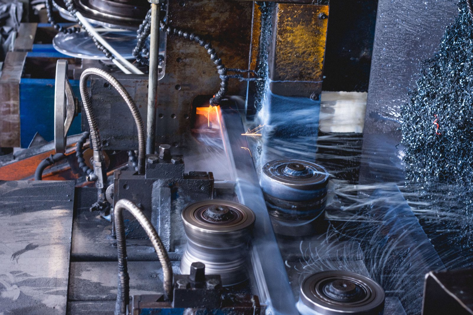
When we scale up from short, simple pipe spools to long, complex runs, the effects of thermal expansion are magnified dramatically. The total displacement increases linearly with length, meaning a 200-meter pipe will expand twice as much as a 100-meter one under the same conditions. This amplified movement transforms from a minor consideration into the dominant factor in the system's mechanical design, introducing risks that threaten the entire infrastructure.
The Accumulation of Force and Stress
The fundamental physics are uncompromising. When a material's natural tendency to expand or contract is blocked, that thermal energy is converted into mechanical stress2. If a pipe is fully restrained at both ends, the resulting axial stress ($\sigma$) can be estimated with the formula $\sigma = E \times \alpha \times \Delta T$, where 'E' is the material's Modulus of Elasticity—a measure of its stiffness. This formula reveals a critical insight: the stress generated is independent of the pipe's length, but the total force is not.
Let's quantify this. For Type 316 stainless steel, the Modulus of Elasticity is approximately 193 Gigapascals (GPa). For the same 80°C temperature change we discussed earlier, the theoretical restrained stress would be enormous—far exceeding the material's yield strength. This means the pipe wouldn't just be stressed; it would be permanently deformed. This is why a fully restrained design for any significant temperature change is fundamentally unworkable. The goal of good design is to prevent this stress from ever building up in the first place by allowing movement.
A manufacturing client integrating a new hot-oil system for a production line learned this lesson practically. Eager to meet a tight deadline, their installation team rigidly welded a long service pipe between two main structural beams, assuming the heavy steel would hold it. The first time the system was brought up to its operating temperature of 180°C, a loud groaning sound was heard from the pipe rack, and the pipe itself was found to have visibly bowed sideways between its supports—a classic and dangerous sign of compressive stress overload.
Pipe Buckling: A Catastrophic Failure Mode
The most dramatic and dangerous failure mode resulting from unchecked compressive stress is pipe buckling3. This is not a simple bending of the pipe; it is a sudden and catastrophic lateral deflection. Buckling is a stability failure, occurring when the axial compressive load exceeds the pipe's structural capacity to resist it. Once buckling begins, the pipe is permanently damaged and the entire line is compromised, requiring immediate shutdown and replacement.
Several factors influence a pipe's susceptibility to buckling. These include the magnitude of the compressive force (a function of $\Delta T$), the pipe's diameter and wall thickness (its cross-sectional strength), and, most importantly, the unsupported length between guides or anchors. Longer, thinner-walled pipes are significantly more vulnerable. The failure is analogous to trying to compress a long, thin drinking straw from both ends; it will inevitably bow out and collapse in the middle.
To prevent this, engineers rely on internationally recognized piping codes such as ASME B31.1 for Power Piping and ASME B31.3 for Process Piping. These codes provide rigorous guidelines for calculating allowable stresses and designing support systems to ensure stability. As a supplier, MFY often works with distributors in Russia and the Middle East who serve clients in the demanding energy and petrochemical sectors. For them, demonstrating full compliance4 with these codes is not just a matter of good practice; it is a non-negotiable requirement for ensuring plant safety and regulatory approval.
Impact on Connected Equipment and Structures
The destructive force of thermal expansion does not remain confined within the pipe. It is relentlessly transferred to everything the pipe is attached to. This includes not only anchors and supports but also high-value, sensitive process equipment such as pumps, compressors, turbines, and pressure vessels. These components are often the heart of an industrial process, and their protection is paramount.
The nozzles on this equipment are particularly vulnerable points. They are designed to withstand process pressure, but not the massive external forces and bending moments that an expanding pipe can impose. Excessive pipe stress can distort the equipment casing, destroy seals leading to leaks, cause critical shaft misalignment leading to premature bearing failure, and in the worst cases, crack the nozzle itself. A 2021 study published in the International Journal of Pressure Vessels and Piping found that uncontrolled pipe stress was a contributing factor in over 30% of premature pump failures in process plants.
This force also impacts the facility's civil and structural elements. Pipe anchors must be secured to structures that can handle the loads. I have seen projects where anchors were bolted to floors or walls that were not designed for such forces, resulting in spalled concrete and failed anchor bolts. This is why we consistently advise our Engineering, Procurement, and Construction (EPC) contractor clients to foster close collaboration between their mechanical piping and structural engineering teams. Pipe anchors must be located and designed not just for piping convenience, but for structural integrity, ensuring the loads are safely transferred to the building's foundation.
Thermal expansion causes axial stressПравда
When restrained, thermal expansion converts to mechanical stress following σ = E × α × ΔT formula.
Pipe length affects stress magnitudeЛожь
Stress depends on material properties and ΔT, but total force accumulates with pipe length.
What are the potential risks if thermal expansion is not adequately managed?
Do you believe that a small amount of pipe movement is a minor operational issue that can be safely ignored? This misconception is perilous. Neglecting to manage thermal expansion can trigger a devastating chain reaction of failures, from persistent leaks and damaged machinery to complete system shutdowns.
Unmanaged thermal expansion introduces severe risks, including catastrophic pipe buckling, weld and gasket failures causing hazardous leaks, and irreparable damage to the nozzles of connected equipment. These failures inevitably lead to costly operational downtime, extensive repairs, and critical safety hazards for plant personnel.
The consequences of these failures extend far beyond the immediate mechanical breakdown. For the clients we serve in highly regulated sectors, such as the pharmaceutical or semiconductor industries5, the risks are magnified. A single, minuscule leak in a high-purity gas or water line, caused by thermal stress on a joint, can compromise an entire production run, leading to the loss of millions of dollars in product and triggering a rigorous, time-consuming re-validation process with regulatory bodies. I recently spoke with a client partner in Asia's pharmaceutical manufacturing sector who faced this exact scenario. A failed gasket on a hot WFI (Water-for-Injection) line, stressed by repeated thermal cycles, forced a four-day shutdown of their main production hall. This real-world example vividly illustrates that the consequences are multi-layered, impacting operational uptime, financial performance, and brand reputation. It transforms the discussion from a technical problem to a critical business risk that demands a comprehensive mitigation strategy.
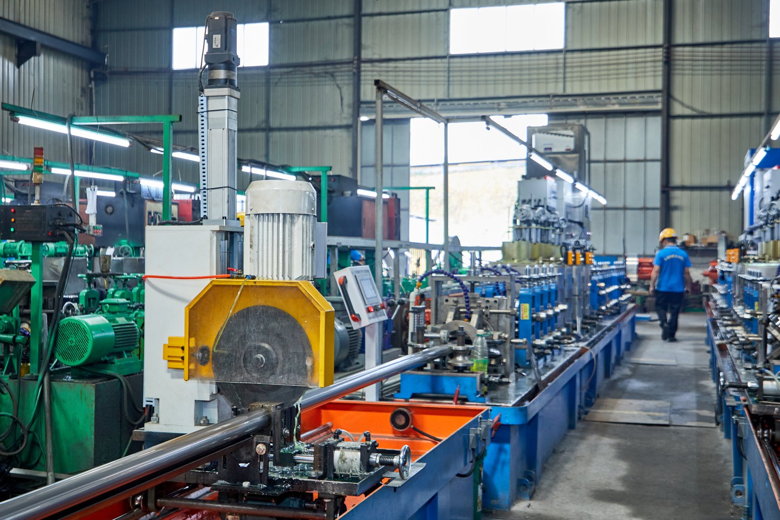
A failure to account for thermal expansion is not a single, isolated error but a fundamental design flaw that can permeate an entire system, creating a web of interconnected risks. These risks can be broadly categorized into three critical areas: direct structural and mechanical failures, cascading operational and financial consequences, and most importantly, severe safety and environmental hazards. Understanding the full spectrum of this jeopardy is essential for appreciating why proactive management is non-negotiable.
Structural and Mechanical Failures
The most direct risk is the physical failure of the piping system itself. As discussed, catastrophic pipe buckling is the most dramatic example, where the pipe itself is destroyed under compressive load. However, more insidious failures can occur at connection points. Welds6, which are metallurgical transition zones, are points of high-stress concentration. Cyclic thermal stress can lead to weld fatigue and the initiation of cracks that can propagate over time, eventually leading to a complete fracture. Similarly, flanged connections rely on gasket pressure to maintain a seal. Pipe expansion can impose huge bending moments on these joints, leading to uneven gasket loading, loss of seal, and persistent leaks.
The failure of the support system is another primary mechanical risk. Pipe anchors and guides are engineered to withstand specific loads. If the actual force generated by thermal expansion exceeds this design load, the support will fail. An anchor bolt can be pulled from its concrete footing, or a steel support member can be permanently deformed. This often creates a domino effect; the failure of one support transfers its load to adjacent supports, which are now also overloaded, potentially leading to a progressive collapse of a section of the pipe rack.
This was starkly illustrated in a district heating project in a cold-climate region that one of our European partners consulted on. The system was installed in the summer, but the designers failed to account for the extreme temperature drop in winter. The resulting thermal contraction put the piping system into immense tension. Several intermediate guide supports, not designed for such tensile loads, failed. This caused the long, heavy pipes to sag dangerously, a condition known as catenary sagging, which in turn put enormous stress on the remaining anchors and the sensitive expansion joints, pushing the entire system to the brink of a major failure.
Operational and Financial Consequences
Beyond the physical damage, the business impact of a failure is severe. The most immediate consequence is unplanned and often prolonged downtime. A ruptured pipe or a damaged pump means the entire process it serves must be halted. In a 24/7 manufacturing facility, the cost of lost production can quickly run into the hundreds of thousands, or even millions, of dollars—a sum that often dwarfs the cost of the physical repair itself.
The direct costs of repair are also substantial. The process involves not just replacing a section of pipe but also securing the area, draining and cleaning the system, potentially hiring specialized certified welders, and conducting non-destructive testing on the new welds. A 2023 report from the Global Manufacturing Council noted that the indirect costs of industrial equipment failure, which include lost productivity and supply chain disruptions, are typically five to ten times higher than the direct "wrench time" cost of the repair.
For our distributor and trader clients, these failures have a reputational cost. Their business is built on supplying reliable, high-quality products. If they provide materials for a project that subsequently fails due to a design flaw related to thermal expansion, it can erode the end-user's trust in their brand, even if the material itself was not faulty. This is a key reason why we at MFY view our role as more than just a supplier. We see ourselves as technical partners, committed to providing the detailed data and support our clients need to ensure their projects are successful and their reputation is protected.
Safety and Environmental Hazards
This is, without question, the most critical and gravest risk. If a pipeline carrying high-pressure steam, flammable hydrocarbons, or corrosive chemicals fails catastrophically, the consequences can be life-threatening for anyone in the vicinity. A sudden release of high-pressure steam can cause severe burns and create a disorienting, hazardous environment. A fracture in a chemical line can release toxic fumes, endangering both plant personnel and the surrounding community.
Even when the fluid is non-toxic, such as hot water or glycol, a sudden rupture presents a significant safety risk. It can create slip hazards, cause severe burns, and damage nearby electrical equipment, creating a secondary risk of fire or electrocution. From an environmental standpoint, a spill from a failed pipeline can be disastrous. A breach in a fuel oil line or a chemical transfer pipe can lead to soil and groundwater contamination, resulting in massive cleanup costs, heavy fines from regulatory bodies like the EPA or their international equivalents, and long-term damage to the company's public image.
We work closely with numerous equipment integrators who design and build modular process skids for the petrochemical industry. For them, safety is the overriding design principle. They meticulously model thermal expansion in their compact designs, often using sophisticated 3D pipe routing to create inherent flexibility. They know that building in solutions like pipe loops to absorb thermal movement is not an option, but a fundamental requirement for delivering a system that is robust, compliant, and, above all, safe for people and the environment.
Thermal expansion causes weld fatigueПравда
Cyclic thermal stress leads to micro-cracks in welds that propagate over time, eventually causing complete fractures.
Pipe anchors prevent all movementЛожь
Anchors only resist movement in specific directions; thermal forces exceeding design loads can still cause support failures.
What measures can be implemented to accommodate thermal expansion in long pipe runs?
Knowing the risks is one thing, but how do you actively prevent them? If you're faced with designing a long pipe run, you need a toolbox of proven solutions. Relying on the pipe's inherent flexibility alone is rarely sufficient or safe for significant temperature changes.
To accommodate thermal expansion, engineers implement flexibility solutions. These include installing expansion loops or offsets (Z-bends), which allow the pipe to flex naturally. Alternatively, manufactured devices like metallic bellows or slip-type expansion joints can be used to absorb movement in a controlled manner.
Choosing the right method to manage thermal expansion is a critical design decision that balances cost, space, and system requirements. There is no single "best" solution; the optimal choice depends entirely on the specific application. During a consultation for a major manufacturing plant expansion, the client was struggling with a long, straight utility corridor where process pipes needed to run. Space was extremely limited, making large expansion loops impractical. Their initial thought was to use numerous expansion joints, but they were concerned about the long-term maintenance burden. This situation perfectly illustrates the engineer's dilemma: a trade-off between spatial footprint, initial cost, and lifecycle reliability. We worked with them to analyze the different process lines. For high-pressure steam, a meticulously designed, compact Z-bend offset proved most reliable. For lower-pressure water lines, a high-quality bellows joint was the more cost-effective choice. This collaborative approach ensures the solution is not just technically sound but also aligned with the client's operational and financial goals.
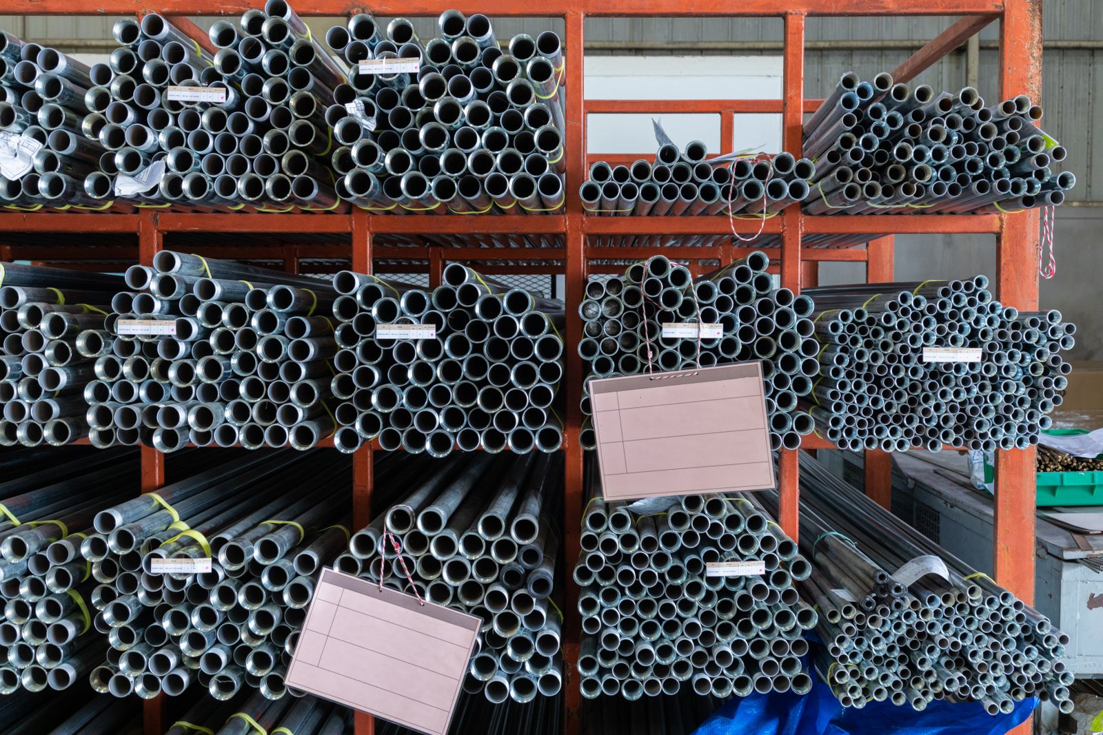
Effectively managing thermal expansion is an exercise in providing controlled flexibility. The core principle is to design a system where the pipe is allowed to grow and shrink without generating harmful stress on itself or connected equipment. This is achieved by transforming the pipe from a rigid, unyielding element into a flexible component. The methods to achieve this range from clever geometric layouts to the integration of specialized mechanical devices, all supported by a robust system of anchors and guides.
Geometric Flexibility: Expansion Loops and Offsets
The simplest and often most reliable method for absorbing thermal movement is to design flexibility directly into the piping layout itself. Instead of a straight line between two points, the pipe is routed with intentional changes in direction, such as offsets or loops. When the pipe expands, these right-angled corners allow the long straight sections to flex laterally, absorbing the linear growth much like a bent paperclip can be pulled and pushed. This method is highly favored in process industries because it uses the pipe itself as the spring, requiring no special components that could fail or require maintenance.
An expansion loop is a large, purpose-built U-shape or rectangular offset installed in a long, straight run of pipe. The dimensions of the loop—its width and length—are carefully calculated by stress engineers to provide enough flexibility to absorb the calculated thermal expansion without over-stressing the pipe material. While highly effective and reliable, the primary drawback of expansion loops is the significant amount of physical space they require, which may not be available in crowded industrial plants or on compact equipment skids.
A simpler variation is the Z-bend or L-bend offset. By routing a pipe with a change in direction, inherent flexibility is created. A long straight run connected to a shorter leg at a 90-degree angle can absorb a surprising amount of movement. Many skilled pipe designers can route systems through a facility, using the required changes in direction to their advantage to manage thermal growth without needing dedicated loops. As a rule, the longer the flexible leg is relative to the expanding leg, the more movement it can safely absorb.
Mechanical Flexibility: Expansion Joints
When space is at a premium and geometric solutions are not feasible, engineers turn to manufactured expansion joints. These are specialized devices inserted into the pipeline that are designed to compress or extend, absorbing thermal movement in a controlled, predictable way. They offer a compact solution to managing expansion but introduce new considerations regarding maintenance and system design. There are several types, the most common being metallic bellows and slip-type joints.
Metallic bellows expansion joints consist of one or more convoluted diaphragms (the bellows) made from thin, flexible stainless steel or other alloys. The bellows is designed to deform under axial, lateral, or angular movement. They are highly effective and can be designed for high pressures and temperatures. However, they are also the most delicate part of the pipeline. They must be protected from torsion and over-extension, requiring a very precise system of pipe anchors and guides to ensure the pipe moves exactly as intended. A failure in the guide system can quickly lead to a catastrophic failure of the bellows.
Slip-type expansion joints consist of two telescoping pipes with a packing or seal system to prevent leaks. As the pipe expands, one pipe simply slides inside the other. They can accommodate very large amounts of axial movement, making them suitable for extremely long pipe runs, such as those found in district heating systems. Their primary disadvantage is the reliance on the packing material, which can wear over time and require periodic maintenance or replacement to prevent leaks. The choice between a bellows and a slip joint often comes down to the fluid being transported (to ensure material compatibility) and the facility's tolerance for maintenance.
The Critical Role of Anchors and Guides
Flexibility solutions cannot work in isolation. They must be supported by a correctly engineered system of anchors and guides. This support system is what directs the thermal expansion into the flexible components where it can be safely absorbed. Without proper anchoring and guiding, the pipeline will move in unpredictable ways, rendering expansion loops and joints ineffective and potentially creating new stress points.
Main anchors are robust structural points that rigidly fix the pipe, preventing all movement and rotation. They are typically installed at the ends of pipe runs and near sensitive equipment to protect it from pipe forces. These anchors are the "fixed points" from which the pipe expands, and they must be designed to withstand the full anchor load generated by the system, including forces from expansion joints. Intermediate anchors can be used to divide a very long pipeline into smaller, more manageable expanding sections.
Pipe guides are supports that allow the pipe to move freely along its axis but prevent it from moving laterally or buckling. They are critical for ensuring that expansion is directed straight into an expansion joint or that an expansion loop flexes in the proper plane. A common error I’ve seen is the use of simple U-bolts as guides; these can bind on the pipe, restraining movement and inadvertently creating a high-stress fixed point. True pipe guides should be designed to be low-friction and to not restrict the desired axial movement. The spacing and design of guides are just as important as the design of the expansion loop or joint itself.
Expansion loops absorb thermal movementПравда
Expansion loops are designed to flex and absorb thermal expansion through geometric flexibility.
Bellows joints require no maintenanceЛожь
Bellows joints are delicate and require proper anchoring and guiding to prevent failure.
What are the best practices for designing pipe systems with thermal expansion considerations?
Are you ready to move from theory to execution? A successful piping system requires more than just knowing the solutions; it demands a disciplined design process. Simply adding an expansion loop without proper analysis is a recipe for failure. Let's outline the professional best practices.
Best practices for pipe design include performing a formal pipe stress analysis, especially for long runs or critical systems. This involves using specialized software to model thermal loads, collaborating closely between piping and structural teams, and considering the full operational lifecycle temperature range.
Adopting a rigorous, process-driven approach is what separates world-class engineering from amateur guesswork. I recall a project with an EPC contractor working on a new power generation facility. From day one, their project charter mandated formal pipe stress analysis for any line operating above 150°C or with a nominal pipe size over 4 inches. This wasn't a response to a problem; it was a proactive policy to prevent problems from ever occurring. Their lead engineer rightly described it as "an investment, not a cost." By using analysis software early in the design phase7, they could optimize pipe routes, minimize the need for expensive expansion joints, and precisely calculate the loads on their pipe rack. This allowed them to reduce steel tonnage in the rack design, and the cost savings from that alone more than paid for the engineering analysis hours. This exemplifies the ultimate best practice: treating thermal design not as a final check, but as an integral part of an optimized and safe design workflow.
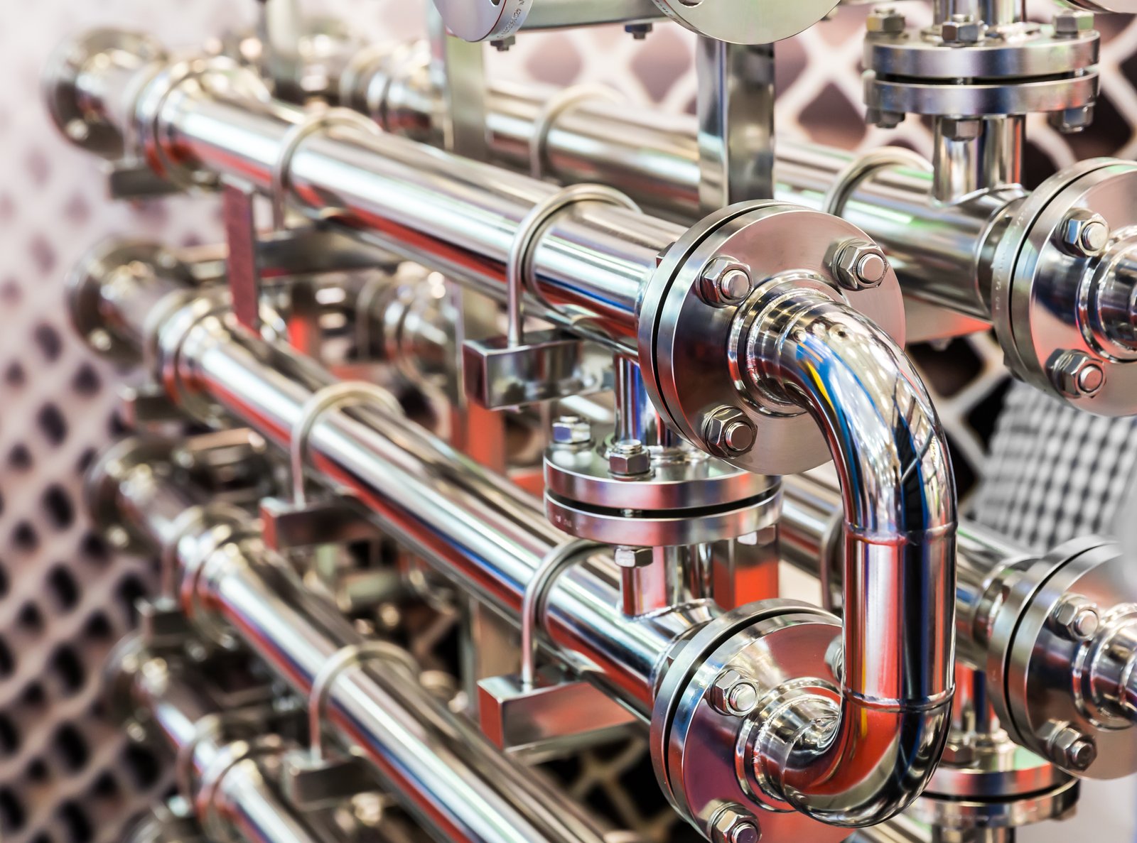
Best practices in piping design are about mitigating risk and optimizing for safety, reliability, and cost-effectiveness. It involves a systematic workflow that begins with data collection and proceeds through analysis, collaboration, and documentation. For any company involved in manufacturing, construction, or equipment integration, institutionalizing these practices is a hallmark of quality and professionalism. At MFY, we support our clients by providing the accurate material data that serves as the foundation for this critical engineering work.
Formal Flexibility and Stress Analysis
The cornerstone of modern pipe design for critical systems is formal flexibility and stress analysis. This is the process of building a mathematical model of the piping system and applying loads to it—including thermal expansion, pressure, and weight—to calculate the resulting stresses, displacements, and loads on equipment. While experienced engineers can often design non-critical, small-bore systems by rule of thumb, this approach is inadequate for long runs, high temperatures, large diameters, or systems connected to sensitive machinery.
This analysis serves several key purposes. First and foremost, it verifies that the stresses within the piping system remain below the allowable limits defined by codes like ASME B31.3. This ensures the system will not fail due to over-stress or fatigue. Second, it calculates the precise displacements at all points in the system, confirming that the pipe will not interfere with other structures or equipment as it moves. ly, it calculates the exact forces and moments that will be exerted on equipment nozzles and structural anchors, allowing the equipment and structures to be designed or verified accordingly.
Today, this analysis is almost exclusively performed using specialized computer software. Programs like CAESAR II, AutoPIPE, and ROHR28 are industry standards. These tools allow engineers to build a 3D model of the pipeline, input material properties (like CTE and Modulus of Elasticity from MFY data sheets), define temperatures and pressures, and run complex simulations in a matter of hours. The output provides a clear pass/fail report against code compliance, making it an indispensable tool for validation and documentation.
Early and Continuous Inter-Disciplinary Collaboration
Effective pipe design is not a siloed activity. It requires constant communication and collaboration between multiple engineering disciplines, primarily mechanical/piping and civil/structural. This collaboration must begin at the earliest stages of the project layout and continue throughout the detailed design phase. Too often, the piping layout is finalized before the structural team has had a chance to evaluate the impact of anchor loads, leading to costly rework.
The piping designer is focused on routing the pipe to connect equipment efficiently, while the stress engineer is focused on ensuring the system's mechanical integrity. Meanwhile, the structural engineer must design the pipe racks and foundations to safely support the pipe's weight and all the dynamic loads it imposes, including those from thermal expansion. For example, the stress engineer might determine that a large expansion loop is needed. This information must be relayed immediately to the layout designer, who must find space for it, and the structural engineer, who must design the supports for this heavier, more complex configuration.
I have seen the success that comes from this integrated approach with our most sophisticated EPC clients. They often use shared 3D plant models where all disciplines can work concurrently. When the piping designer places an anchor, the resulting load calculated by the stress analyst is automatically populated into the structural model, instantly flagging any potential overloads. This seamless flow of information prevents errors, accelerates the design cycle, and ultimately results in a safer, more cost-effective plant.
Designing for the Entire Lifecycle
A final best practice is to consider the entire operational lifecycle of the piping system when defining the design parameters. This means looking beyond just the normal operating temperature. The design must account for a range of potential scenarios, including start-up and shutdown conditions, emergency or upset conditions, and any maintenance procedures like steam cleaning.
For example, a pipe might operate at 200°C but be subject to steam cleaning at 250°C. The thermal expansion and stress analysis must be run for the 250°C case, as this represents the highest stress condition. Similarly, a system installed in a hot climate like the Middle East might be installed at an ambient temperature of 45°C but could be shut down and cooled by a process fluid to 10°C. This large temperature drop will cause significant contraction, putting the system into tension, which must also be analyzed.
Furthermore, engineers must consider cyclic conditions. A system that is heated and cooled once a day (e.g., for a batch process) will experience tens of thousands of stress cycles over its lifespan. This requires a fatigue analysis to ensure the pipe material and welds can withstand this repeated flexing without failing. By designing for the most extreme conditions and the total number of cycles, we ensure the system is not just safe on day one, but remains safe and reliable for its entire intended service life of 20 or 30 years.
Stress analysis prevents pipe failuresПравда
Formal pipe stress analysis ensures stresses remain below allowable limits, preventing failures from over-stress or fatigue.
Piping design is a solo activityЛожь
Effective pipe design requires continuous collaboration between mechanical, piping, and structural engineering teams.
Заключение
Ultimately, managing thermal expansion in stainless steel pipes is a fundamental requirement for safety and reliability. Proactive design, leveraging flexibility solutions like loops or joints, and performing rigorous stress analysis are essential for creating durable, cost-effective systems that stand the test of time.
-
Discover the impact of thermal expansion on stainless steel pipes' durability and performance. ↩
-
Understand how blocked thermal expansion converts to stress in restrained pipes. ↩
-
Discover the risks of pipe buckling due to axial loading and design considerations. ↩
-
Explore ASME standards ensuring stability in piping systems through compliance. ↩
-
Understand industry-specific risks and implications of inadequate thermal expansion management ↩
-
Discover how thermal stress impacts weld integrity and potential failures ↩
-
Understand the cost and efficiency benefits of early analysis in piping projects ↩
-
Discover industry-standard tools for pipe stress analysis and validation ↩
У вас есть вопросы или нужна дополнительная информация?
Свяжитесь с нами, чтобы получить индивидуальную помощь и квалифицированный совет.
